EWK

  • VENTILAÇÃO AXIAL
  • CIRCUITO ABERTO

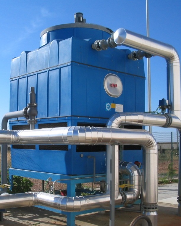
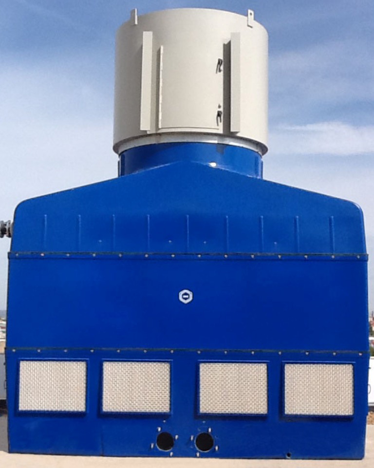
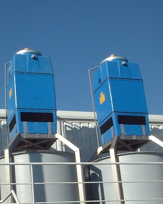
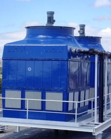
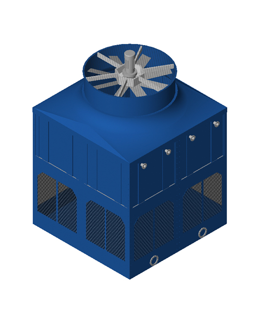
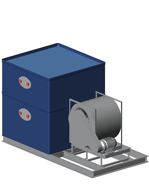
Torre de resfriamento de circuito aberto, pré-montada em fábrica:

  • Ampla faixa de capacidade: de 4 a 500 m³/h
  • Design modular
  • Enchimentos de fluxo laminar e por gotejamento
  • Carcaça em poliéster reforçado com fibra de vidro
  • Resistente à corrosão
  • Engenharia alemã
  • Materiais de alta resistência a condições agressivas e temperaturas extremas
  • Baixo consumo de energia
  • Pré-montada em fábrica / Fácil instalação
  • Enchimento padrão em polipropileno com tratamento antilegionela (SANIPACKING®) –

DOWNLOAD

EWK Smart Option

1
2
3
4
5
6
7
8
9
10
11
12
13
14
15
16
17
18
19
20
21
1

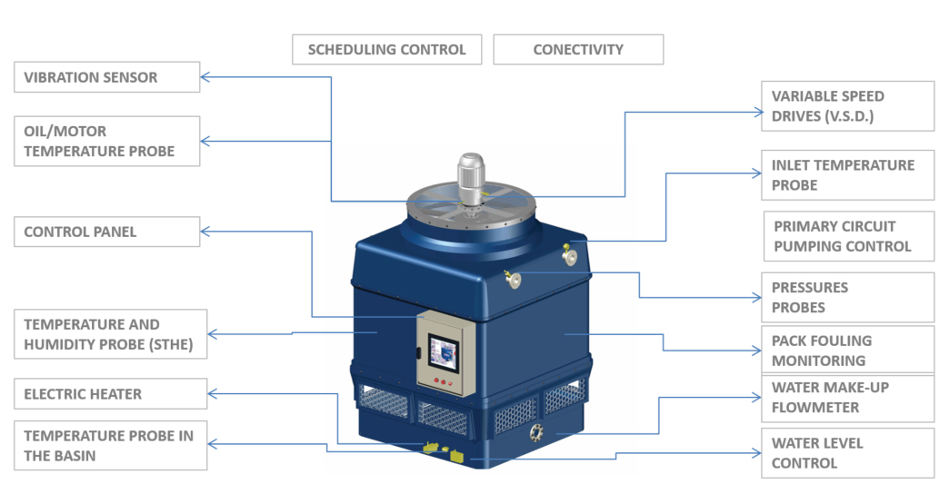
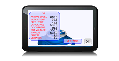
VARIABLE SPEED DRIVES (VSD)
VSD´s adjusts the rotation speed of the fan motors according to the parameters set on the control panel. This device integrates the control software with PID algorithms, which optimize energy consumption and recommend preventive maintenance. The VSD is able to monitor the following useful information about the motor:

– Motor rotation speed.
– Current through the motor coils.
– Voltage.
– Real electric consumption, etc.

2

PRIMARY CIRCUIT PUMPING CONTROL
Regulation of the primary circuit pumping according to the process parameters.

3

WATER MAKE-UP FLOWMETER
This device records the amount of make-up water that is fed into the cooling tower.

4

PACK FOULING MONITORING
The “Smart Cooling Tower” can detect the accumulation of dirt, lime scale, biological film, etc. within the packing. The control panel monitors the level of fouling and can advise when the pack needs to be cleaned or replaced. This avoids any loss of thermal performance due to fouling.

5

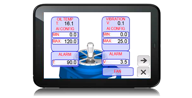
OIL / MOTOR TEMPERATURE PROBE
This sensor measures vibrations in the fan/motor set in real time. If abnormal vibration is detected it can send an alarm signal or even stop the fan. This way we will prevent damage to the fan.

6

WATER LEVEL CONTROL
This sensor is located in the water basin and constantly monitors the water level and compares it against the set high and low level parameters. The sensor will send high and low level alarms to the control panel should the water level fall out of the set parameters, preventing the sump from draining down or overflowing. Additionally, in the event of a low level alarm the control panel will switch off the electric heater so as not to damage the casing. When the level is normal the equipment works with no restriction.

7

VIBRATION SENSOR
This sensor measures vibrations in the fan/motor set in real time. If abnormal vibration is detected it can send an alarm signal or even stop the fan. This way we will prevent damage to the fan.

8

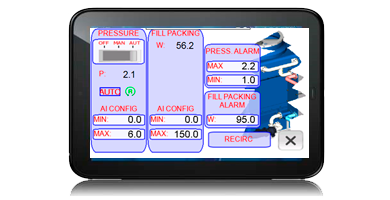
PRESSURE PROBES

9

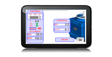
ELECTRIC HEATER
This heating element is designed to heat the water in the area closest to the cooling tower discharge, thus ensuring that the pumps are not starved of water upon start up. Thanks to this device, the water in the sump is prevented from freezing avoiding damage to hydraulic elements. The control panel can set the maximum and minimum temperature and the required hysteresis in the sump.

10

CONECTIVITY
Using a Modbus TCP/IP (two way) communication system, full remote access of the ”Smart Cooling Tower” is possible anywhere in the world using a PC or smart device. This system allows full monitoring of the towers functionality and ensures that any alarms are received and actioned by key personnel on or off site.

11

VARIABLE SPEED DRIVES (VSD)

12

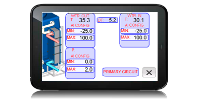
INLET TEMPERATURE PROBES

13

INLET TEMPERATURE PROBES
Inlet temperatures are constantly monitored using built in temperature probes. The control panel uses the temperatures obtained to optimize the tower functionality and control using the VSD

14

VIBRATION SENSOR / TEMPERATURE PROBE

15

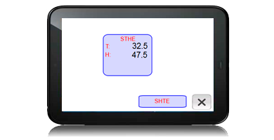
TEMPERATURE AND HUMIDITY PROBE (STHE)

16

ELECTRIC HEATER

17

PRESSURE PROBES
PRIMARY: Allows accurate monitoring of the process water flow rate.

18

CONTROL PANEL
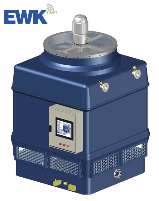
The control panel oversees and monitors the autonomous management of the ”Smart Cooling Tower”, based on the set parameters and the information gathered from the various probes installed. The main component is a PLC that integrates algorithms PID to optimize the power consumption of the fan motors and circulating pumps motors, according to the set-point values introduced. Please note that the circulating pumps are only available on our closed-circuit tower range.

The control panel comes as standard with a 7” touch screen, allowing full operational control of the ”Smart Cooling Tower”. As an optional extra the screen size can be increased to 10”.

19

TEMPERATURE AND HUMIDITY PROBE (STHE)
The Temperature and Humidity sensor monitors the outdoor conditions around the cooling tower, making it possible to remotely appraise the performance of the ”Smart Cooling Tower”, based on the design criteria.

20

SCHEDULING CONTROL
Using the ”Smart Towers” scheduling capabilities to only run the tower during set periods of the day, reduces energy consumption over a 24hr period. As a result, less energy is used and lower noise levels are observed during off peak hours when there is less demand for heat rejection.

21

TEMPERATURE PROBE IN THE BASIN
It is installed at the sump to monitor the cold-water temperature. This probe controls the operation of the electric heater in the sump.

Princípios de funcionamento

As torres de refrigeração fazem com que uma massa de ar frio e seco circule em contracorrente à água quente proveniente de um processo industrial ou de climatização. Parte dessa água evapora, arrefecendo o restante. O calor necessário para este processo é de aproximadamente 597 kcal/litro. A água arrefecida resultante regressa ao processo para reiniciar o ciclo. Os equipamentos que operam com este princípio de arrefecimento evaporativo são fundamentais para a eficiência energética.

A diferença entre a temperatura desejada da água arrefecida e a temperatura de bolbo húmido (denominada “aproximação” ou *approach*) é um fator determinante para o dimensionamento da torre. Quanto menor for esta diferença, maior deverá ser a área de permuta térmica. Esta diferença deve ser de, pelo menos, 3 a 4 °C. Nas torres de refrigeração de circuito aberto, ocorre um contacto direto e intenso entre a água e o ar, potenciado pela utilização de enchimentos que oferecem uma grande área de troca, melhorando assim o desempenho e a evaporação. Existem diferentes tipos de enchimento, adequados a diferentes qualidades de água.

Equipamento adicional

  • Carcaça em PRFV com tratamento SANIPACKING®
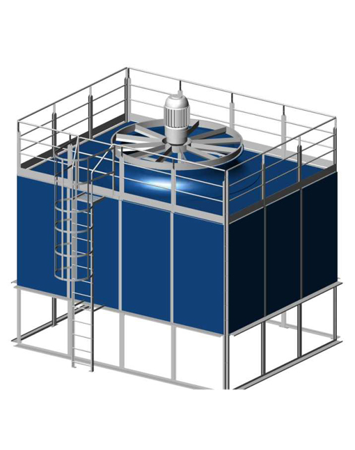
  • Escada de acesso e guarda-corpos para o motor do ventilador
  • Porta de acesso em polipropileno
  • Interruptor de vibração para o equipamento de ventilação
  • Conversores de frequência para o motor elétrico
  • Sensor PTC para o motor
  • Silenciador de escape
  • Ventilador de baixo ruído
  • Sensores de nível de água na bacia
  • Embalagem de inverno (termóstato e aquecedor de imersão) para proteção contra baixas temperaturas
  • Sistema de dosagem para tratamento de água
  • Atenuadores de ruído de queda de água na bacia

Características técnicas

Model *Dissipation
kw
Empty weight
kg
Service weight
kg
Fan power
kw
Long
mm
Wide
mm
High
mm
Dim. Drawing Plan DWG
EWK 036/06 46 51 115 0.37 720 615 1745 seleccionar seleccionar
EWK 064/09 100 126 235 0.55 999,5 832 2225 seleccionar seleccionar
EWK 144/09 220 218 490 2.2 1395 1269 2925 seleccionar seleccionar
EWK 225/09 350 355 876 3.0 1690 1557 3100 seleccionar seleccionar
EWK 324/09 503 466 1103 4.0 1971 1850 3425 seleccionar seleccionar
EWK 441/09 696 633 1595 5.5 2330 2150 3459 seleccionar seleccionar
EWK 680/09 1080 1016 3347 7.5 3395 2381 4550 seleccionar seleccionar
EWK 900/09 1320 1131 3917 11.0 4415 2093 4485 seleccionar seleccionar
EWK 930/09 1512 1390 4578 11.0 4235 2381 4690 seleccionar seleccionar
EWK 1260/09 1955 1940 6516 15.0 4285 3395 4770 seleccionar seleccionar
EWK 1800/09 2735 2609 10134 22.0 4605 4300 4805 seleccionar seleccionar

* Heat rejection at the following conditions: Tin: 35,0 ºC, Tout: 30,0 ºC, Twb: 24,0 ºC

a sua fonte de energia

© ENERGETUS