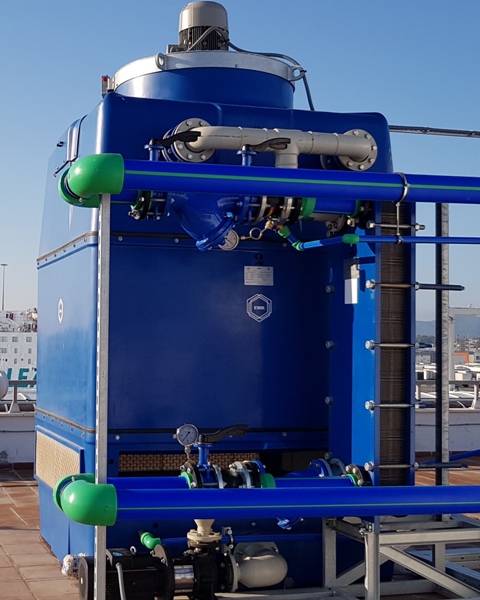
EWK-I
- AXIAL VENTILATION
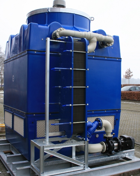
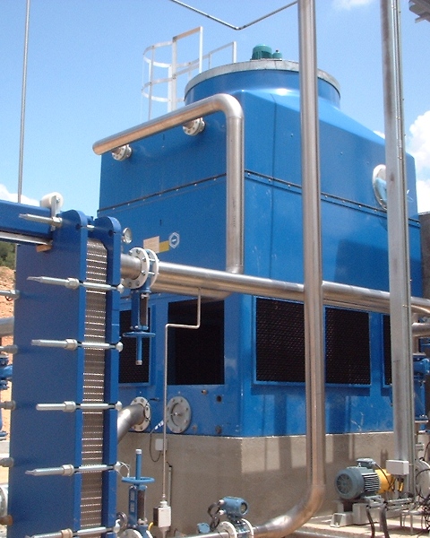
- CLOSED CIRCUIT
Close circuit cooling towers with external stainless steel heat exchanger.
- Low energy consumption
- German engineering
- Compact casing made of fiberglass-reinforced polyester
- Corrosion free
- Direct Transmission (no pulleys or belts).
- Materials highly resistant to extreme temperatures
- Standard Fill materials in Polypropylene with anti-legionella treatment (SANIPACKING®)
- Pre-assembled at the factory / Easy installation
- Easy cleaning
- Y Strainer installed in the secondary circuit to reduce possible contamination of the heat exchanger.
- Distribution pipes in Polypropylene