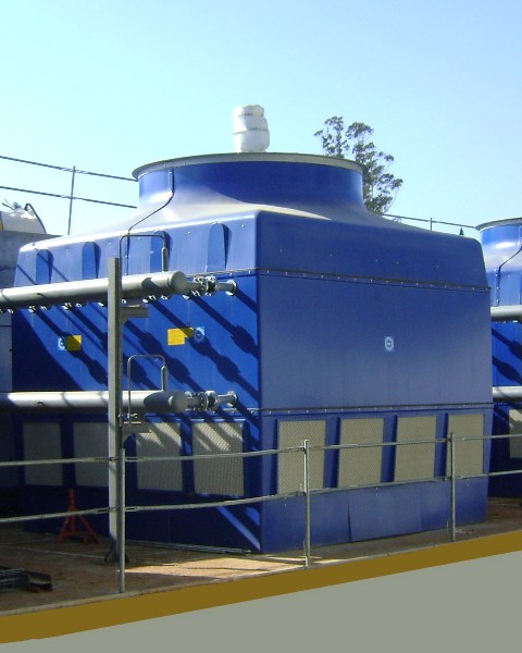
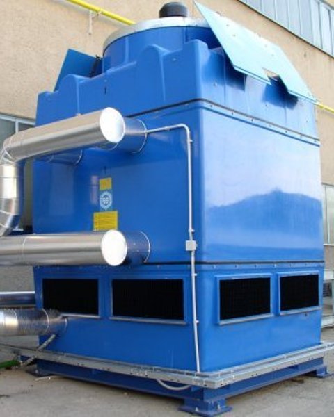
EWK-C

  • AXIAL VENTILATION
  • CLOSED CIRCUIT

Close circuit cooling towers with internal galvanized steel coil
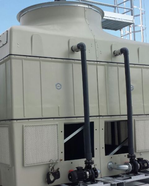
  • Corrosion free
  • German engineering
  • Direct Transmission (no pulleys or belts).
  • Low energy consumption
  • HCS (High Conductivity System) coil, made of hot galvanized steel
  • Refrigerant fluids: Water, oils, glycol, etc.
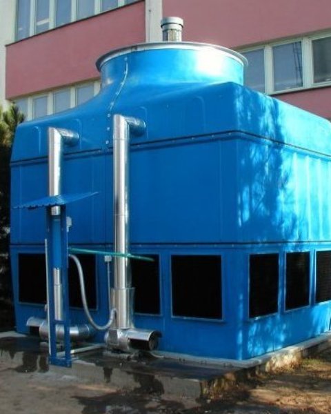
  • Casing made of fiberglass-reinforced polyester
  • Pre-assembled at the factory / Easy to install
  • Materials highly resistant to all aggressive conditions, as well as to extreme temperatures
  • Standard Fill materials in Polypropylene with anti-legionella treatment (SANIPACKING®)

Technical Features

Model *Dissipation
kw
Empty weight
kg
Service weight kg Recirculation pump
kw
Fan power
kw
Long
mm
Wide
mm
High
mm
Dim. Drawing Plan
DWG
EWK-C 144/2 26 650* 1190* 0.75 2.2 2125 1269 2525 seleccionar seleccionar
EWK-C 144/3 52 750* 1250* 0.75 2.2 2125 1269 2825 seleccionar seleccionar
EWK-C 144/4 73 900* 1440* 0.75 2.2 2125 1269 2825 seleccionar seleccionar
EWK-C 225/3 99 1092 1789 0.75 3.0 2522 1557 2990 seleccionar seleccionar
EWK-C 225/4 128 1262* 2024* 0.75 3.0 2522 1557 2990 seleccionar seleccionar
EWK-C 225/5 165 1437 2264 0.75 3.0 2522 1557 3245 seleccionar seleccionar
EWK-C 324/3 180 1466* 2368* 1.5 4.0 2895 1850 3425 seleccionar seleccionar
EWK-C 324/4 203 1697 2695 1.5 4.0 2895 1850 3425 seleccionar seleccionar
EWK-C 324/5 230 1929* 3024* 1.5 4.0 2895 1850 3710 seleccionar seleccionar
EWK-C 441/3 218 1991* 3280* 2.2 5.5 3293 2150 3379 seleccionar seleccionar
EWK-C 441/4 301 2291* 3776* 2.2 5.5 3293 2150 3379 seleccionar seleccionar
EWK-C 441/5 383 2589* 4202* 2.2 7.5 3293 2150 3639 seleccionar seleccionar
EWK-C 441/6 401 2889 4638 2.2 7.5 3293 2150 3869 seleccionar seleccionar
EWK-C 680/3 383 3126* 6070* 4.0 7.5 3941 2319 4550 seleccionar seleccionar
EWK-C 680/4 410 3593* 6743* 4.0 7.5 3941 2319 4820 seleccionar seleccionar
EWK-C 680/5 450 4058 7415 4.0 7.5 3941 2319 4820 seleccionar seleccionar
EWK-C 680/6 490 4525* 8090* 4.0 7.5 3941 2319 5050 seleccionar seleccionar
EWK-C 900/3 492 3640* 7145* 4.0 11.0 4984 2020 4485 seleccionar seleccionar
EWK-C 900/4 555 4189* 7946* 4.0 11.0 4984 2020 4485 seleccionar seleccionar
EWK-C 900/5 559 4739* 8750* 4.0 11.0 4984 2020 4685 seleccionar seleccionar
EWK-C 900/6 639 5290 9554 4.0 11.0 4984 2020 4885 seleccionar seleccionar
EWK-C 1260/3 754 5757* 11453* 2×4.0 15.0 4285 3893 4770 seleccionar seleccionar
EWK-C 1260/4 921 6586 12677 2×4.0 15.0 4285 3893 4770 seleccionar seleccionar
EWK-C 1260/5 1109 7419* 13909* 2×4.0 15.0 4285 3893 4970 seleccionar seleccionar
EWK-C 1260/6 1250 8251* 15138* 2×4.0 15.0 4285 3893 5125 seleccionar seleccionar
EWK-C 1800/3 1046 7516* 16408* 2×4.0 22.0 5123 4300 4805 seleccionar seleccionar
EWK-C 1800/4 1319 8622* 18022* 2×4.0 22.0 5123 4300 5065 seleccionar seleccionar
EWK-C 1800/5 1486 9727* 19631* 2×4.0 22.0 5123 4300 5065 seleccionar seleccionar
EWK-C 1800/6 1610 10832 21242 2×4.0 22.0 5123 4300 5225 seleccionar seleccionar

* Heat rejection at the following conditions: Tin: 35,0 ºC, Tout: 30,0 ºC, Twb: 24,0 ºC

EWK Smart Option

1
2
3
4
5
6
7
8
9
10
11
12
13
14
15
16
17
18
19
20
21
1

VARIABLE SPEED DRIVES (VSD)
VSD´s adjusts the rotation speed of the fan motors according to the parameters set on the control panel. This device integrates the control software with PID algorithms, which optimize energy consumption and recommend preventive maintenance. The VSD is able to monitor the following useful information about the motor:

– Motor rotation speed.
– Current through the motor coils.
– Voltage.
– Real electric consumption, etc.

2

PRIMARY CIRCUIT PUMPING CONTROL
Regulation of the primary circuit pumping according to the process parameters.

3

WATER MAKE-UP FLOWMETER
This device records the amount of make-up water that is fed into the cooling tower.

4

PACK FOULING MONITORING
The “Smart Cooling Tower” can detect the accumulation of dirt, lime scale, biological film, etc. within the packing. The control panel monitors the level of fouling and can advise when the pack needs to be cleaned or replaced. This avoids any loss of thermal performance due to fouling.

5

OIL / MOTOR TEMPERATURE PROBE
This sensor measures vibrations in the fan/motor set in real time. If abnormal vibration is detected it can send an alarm signal or even stop the fan. This way we will prevent damage to the fan.

6

WATER LEVEL CONTROL
This sensor is located in the water basin and constantly monitors the water level and compares it against the set high and low level parameters. The sensor will send high and low level alarms to the control panel should the water level fall out of the set parameters, preventing the sump from draining down or overflowing. Additionally, in the event of a low level alarm the control panel will switch off the electric heater so as not to damage the casing. When the level is normal the equipment works with no restriction.

7

VIBRATION SENSOR
This sensor measures vibrations in the fan/motor set in real time. If abnormal vibration is detected it can send an alarm signal or even stop the fan. This way we will prevent damage to the fan.

8

PRESSURE PROBES

9

ELECTRIC HEATER
This heating element is designed to heat the water in the area closest to the cooling tower discharge, thus ensuring that the pumps are not starved of water upon start up. Thanks to this device, the water in the sump is prevented from freezing avoiding damage to hydraulic elements. The control panel can set the maximum and minimum temperature and the required hysteresis in the sump.

10

CONECTIVITY
Using a Modbus TCP/IP (two way) communication system, full remote access of the ”Smart Cooling Tower” is possible anywhere in the world using a PC or smart device. This system allows full monitoring of the towers functionality and ensures that any alarms are received and actioned by key personnel on or off site.

11

VARIABLE SPEED DRIVES (VSD)

12

INLET TEMPERATURE PROBES

13

INLET TEMPERATURE PROBES
Inlet temperatures are constantly monitored using built in temperature probes. The control panel uses the temperatures obtained to optimize the tower functionality and control using the VSD

14

VIBRATION SENSOR / TEMPERATURE PROBE

15

TEMPERATURE AND HUMIDITY PROBE (STHE)

16

ELECTRIC HEATER

17

PRESSURE PROBES
PRIMARY: Allows accurate monitoring of the process water flow rate.

18

CONTROL PANEL
The control panel oversees and monitors the autonomous management of the ”Smart Cooling Tower”, based on the set parameters and the information gathered from the various probes installed. The main component is a PLC that integrates algorithms PID to optimize the power consumption of the fan motors and circulating pumps motors, according to the set-point values introduced. Please note that the circulating pumps are only available on our closed-circuit tower range.

The control panel comes as standard with a 7” touch screen, allowing full operational control of the ”Smart Cooling Tower”. As an optional extra the screen size can be increased to 10”.

19

TEMPERATURE AND HUMIDITY PROBE (STHE)
The Temperature and Humidity sensor monitors the outdoor conditions around the cooling tower, making it possible to remotely appraise the performance of the ”Smart Cooling Tower”, based on the design criteria.

20

SCHEDULING CONTROL
Using the ”Smart Towers” scheduling capabilities to only run the tower during set periods of the day, reduces energy consumption over a 24hr period. As a result, less energy is used and lower noise levels are observed during off peak hours when there is less demand for heat rejection.

21

TEMPERATURE PROBE IN THE BASIN
It is installed at the sump to monitor the cold-water temperature. This probe controls the operation of the electric heater in the sump.

Working Principles

The fluid to be cooled (usually water) flows through the tubes of the coil without coming into direct contact with the external air, preventing dirt or pollution from entering the primary water circuit. The heat is transmitted from the fluid through the tube walls to the water, which is being continuously sprayed over the coil.

The fan situated at the top of the tower intakes air in counterflow to the water, thereby evaporating a small part of the re-circulating water, drawing off the necessary heat for evaporation and releasing it into the atmosphere. The rest of the water is re-circulated with a spray water pump from the basin to the spray nozzles. (Secondary circuits). A small quantity of heat is transmitted by convection to the external air, just as for an air cooler.

Additional equipment

  • PRFV with SANIPACKING® treatment casing
  • Access ladder & Hand rail to the fan motor
  • Vibration switch for ventilation equipment
  • Electric motor frequency converters
  • PTC sensor for the motor
  • Exhaust silencer
  • Low noise fan
  • Sensors for the level of water in the basin.
  • Winter pack (Thermostat & Immersion heater) to protect from low temperatures
  • Water treatment dosing system
  • Attenuators of noise from the drops in the basin
  • SMART Cooling Tower
your energy source

© ENERGETUS